
Safety factors (SF) exist in engineering because of our inability to determine or predict the actual forces, speeds, or other parameters for a given application. For casters, uneven riding surface, variable speeds, changing turning radius, and changes in load distribution all play a part in the variability of the stresses a caster undergoes during use. So it is prudent to use a safety factor when calculating load and speed ratings for casters.
The required safety factor can vary depending on certain industries’ standards. For example, in aerospace and military applications, customers typically require a 3X safety factor based on the material’s yield stress or a 5X safety factor on the ultimate tensile stress of that material, or whichever is higher. The standards are slightly less strict in some automotive applications, with a 2X on yield and 3.5X on UTS requirement.
Caster Concepts develops many of our products for specific industries, so our SF standards will vary. However, typically we provide load ratings that have a 1.5X SF on functionality, 2X SF on yield, and a 4X SF on UTS. This means our casters remain functional when subjected to 1.5X the catalog load rating. At 2X the catalog load rating, components on the casters will begin to deform, and then at 4X the catalog load rating, expect the caster to start to see catastrophic failure.
Higher SF typically is associated with higher costs. So a higher SF may not always be desirable. The optimal goal is to understand the application variations and ensure that the SF is large enough to accommodate those changes. As always, it is a good idea to talk to Caster Concepts engineers to obtain specific SF on a particular product.
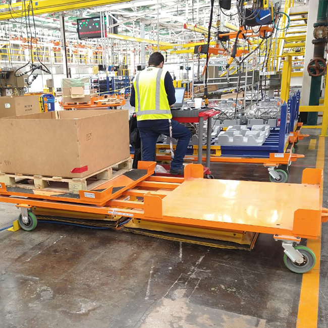
Failure of a caster comes in many forms. At higher speeds, the weakest link is the polyurethane treads. Swivel bearings and wheel bearings typically wear out first at high shock loads. At high static load, caster legs — the pieces of structure which support the wheels — or the wheel axle begin to deform. There are always ways to improve strength depending on failure modes. One way is to utilize higher-performing polyurethanes that do not generate as much heat at a given load and speed. Larger, more shock-resistant bearings can also be used in the design to provide longer life. Using additional material can also reinforce structural members under high stress.
Our engineering teams employ several different methods to determine our products’ safety factors. In the design phase, our engineers use Finite Element Analysis (FEA) to subject our designs to various loading conditions and examine the resulting stresses. FEA allows our engineers to modify our designs to mitigate high-stress areas. Additionally, Caster Concepts has a sophisticated test lab with various test machines, such as a static load tester and a dynamometer. We use each of these machines to simulate actual use conditions to determine the point of failure for each caster. In many cases, we can use the test machines to develop and calibrate failure models, which are then used in the design of casters without the need for physical testing.